2d rendering context
drawable.getContext('2d') returns a context implementing a subset of the
HTML CanvasRenderingContext2D
API. It is backed by the XRender extension: fills, gradients, composition and
glyph drawing are executed on the X server, so pixel data does not travel
over the connection for most operations.
On windows, drawing goes into an offscreen backing pixmap and is presented
in single blits (double buffering — flicker-free by default; see
window.md). On pixmaps the context draws directly.
getImageData reads the backing pixmap on double-buffered windows, so it is
valid even where the window is occluded.
const ctx = wnd.getContext('2d');
ctx.fillStyle = 'rgba(255, 0, 0, 0.5)';
ctx.fillRect(0, 0, 100, 100);
Properties
ctx.canvas— the owning drawable (window or pixmap), like in the browserctx.width,ctx.height— drawable sizectx.fillStyle,ctx.strokeStyle— a CSS color string, a premultiplied[r, g, b, a]array (0..1 floats), aCanvasGradient, aCanvasPattern, or aPicture. Named colors,rgb[a](),hsl[a]()and hex in all four lengths (#rgb,#rgba,#rrggbb,#rrggbbaa) are accepted; anything unparseable throws rather than drawing something arbitrary. The functions take both of CSS Color 4's syntaxes — commas, or spaces with the alpha after a slash (rgb(255 128 0 / 50%),hsl(120deg 50% 50%)), with percentages,noneand any angle unit — and names and functions are case-insensitive. A component out of range is clamped, as CSS clamps it. See Color below for what alpha doesctx.lineWidth,ctx.lineCap,ctx.lineJoin,ctx.miterLimit— stroke geometry, including'round'caps and joins (rendered as triangle-fan disks unioned with the stroke mesh). A join whose inner corner would fall outside the two segments meeting there — a hairpin, or any turn tight relative to how short they are — is built from the segments' own ends instead, so the stroke of a path stays within half a line width of it (plus the miter itself, whichmiterLimitbounds)ctx.setLineDash(segments),ctx.getLineDash(),ctx.lineDashOffset— canvas-spec dashes: an empty list is solid, an odd-length list doubles, negative/non-finite values invalidate the call,getLineDash()returns a copy, and the state participates insave()/restore(). Dashing splits the flattened polyline by arc length, so caps apply to each dash; on closed subpaths the pattern continues around the loop (no cap at the seam unless a gap lands there). Only the part of a path the surface can show is dashed; the rest moves the pattern along by its length, so a dashed border round a box far taller than the window costs what the window shows. A pattern that would still make more than 100,000 dashes there is stroked solid, as Chrome's Skia strokes one: dashes that fine are a tonectx.globalAlpha— multiplies everything drawn: fills, strokes,fillRect,drawImage, text (fillText,drawGlyphsand soTextLayout.draw) and the shadows they cast. At0nothing is drawnctx.fadesGlyphs—true: text honoursglobalAlpha, as above. A read-only feature test for code handed contexts it did not make. Older ntk drew glyphs at full opacity whatever the alpha, and another backend's context answers for itself; where this is nottrue, text has to be faded some other way, such as drawing it on a surface and fading thatctx.takesColorSources—true:drawGlyphsanddrawTrapstake a colour forsrcas well as a picture — a CSS colour string, a premultiplied[r, g, b, a], ornullforfillStyle— and paint it with a solid theAppfrees as colours change. A read-only feature test, likefadesGlyphs: older ntk took a picture only, and a colour drew nothing; where this is nottrue, make the source withcreateSolidPicture. See text.mdctx.shadowColor,ctx.shadowBlur,ctx.shadowOffsetX,ctx.shadowOffsetY— drop shadows, off by default (a transparentshadowColor). See Shadows belowctx.globalCompositeOperation— Porter-Duff subset mapped to XRender ops:source-over(default),copy,destination-over,source-in,destination-in,source-out,destination-out,source-atop,destination-atop,xor,lighter. Everything drawn takes it: fills, strokes, rectangles, images, text (fillText,TextLayout.draw) and the shadows they cast. The ops that write where a drawing has no ink clear the rest of the drawing's own box, not the surface, and no op changes a pixel outside the clip — see Composite ops that clearctx.font— the CSSfontshorthand ('bold italic 40px "DejaVu Sans"'), resolved through fontconfig; see fonts.md. Style, weight,small-capsand a stretch keyword come in any order before the size; a/line-heightafter it is read and ignored, as canvas ignores it; sizes take any CSS length,emand%against the 20px a context starts with; and the whole family list is kept, so a letter the first family lacks is set in the next ('16px "Some Font", serif'). A string that is not a font is ignored and the font stays what it was
Everything that puts ink on the surface goes through the clip: fills,
strokes, images, text (fillText, TextLayout.draw) and the vector shapes
SvgView draws. A rectangular clip stack never becomes a mask. It is
either a rectangle handed to the server around the drawing
(SetPictureClipRectangles) or — where the drawing is a single composite of
a box, as fillRect and drawImage are — the same rectangle intersected
into that box, which costs no requests and no pixels at all. That is what
makes a renderer's save()/clip(damage)/…/restore() frame cheap. A
rectangle of no width or no height is one too — a box of no height clipping
its content — and nothing is drawn through it.
Non-rectangular clips build an a8 mask, and an XFIXES region is a third kind
the server applies itself — see Region clips. Where a mask
is genuinely needed, the work it costs is bounded to the box the drawing
composites, not the surface: a translucent fill inside a rounded-corner clip
pays for its own rectangle.
Where the rectangle does go to the server it is context state, not a per-drawing stamp: a second drawing under a clip the picture already carries sends no clip request at all, and neither does a repaint of the same damage rectangle on the next frame. A rounded box under a damage clip — a fill and a border, each of them corner glyphs plus strips — costs one clip request rather than four.
Nothing outside the clip changes, whatever globalCompositeOperation is.
The ops that write where a drawing has no ink — copy, source-in,
destination-in, source-out and destination-atop — take a rectangle or a
region the way every other op does, and a path clip after the op rather than
through the mask: see Composite ops that clear.
Composite ops that clear
copy, source-in, destination-in, source-out and destination-atop
write where a drawing has no ink — the source, or nothing — so they clear
pixels the drawing does not cover. How far that reaches is the drawing's own
box: the rectangle fillRect or drawImage covers, and for a path, a stroke
or text the box round its ink, out to whole pixels and one past them for the
antialiased edge. Nothing outside that box changes, where a browser's canvas
clears every pixel the clip lets through.
Nor does anything outside the clip, as the canvas spec requires of every op.
A rectangular clip or a region cuts the box these ops clear, as it cuts any
drawing. A path clip is applied after the op, as a browser applies one: a
pixel inside the clip gets what the op makes of it, a pixel outside keeps
what it had, and a pixel on the clip's antialiased edge goes part of the
way, as far as the clip covers it. RENDER has no operator for that: through
a mask, copy is the source times the mask, so a clip folded into the
mask would clear every pixel of the box it leaves out. Under a path clip
these five ops draw onto a copy of their box instead, cut to the clip's
bounding box, and bring the copy back through the clip's coverage, which
costs a scratch pixmap the size of that box and three composites on top of
the drawing's own. The other ops take a path clip in their mask, which for
them comes to the same pixels at no extra cost.
Text clears the box round every glyph of the call, as a fill clears the box
round every subpath, and applies the op once, through the coverage of all of
them, on whichever route it takes: a glyph's ink is never cleared by the box
of the glyph beside it. The clip cuts that box as it cuts a path fill's. A
TextLayout whose spans change colour draws once per colour, as that many
fillTexts would, so under copy each colour clears the rest of its own
box, the text of the colours before it included.
Color
XRender colors are premultiplied: each of r, g and b is already
scaled by a, so all three must be <= a. Color strings are converted
for you — 'rgba(255, 0, 0, 0.5)' reaches the server as
[0.5, 0, 0, 0.5] — but an array is taken as already premultiplied and
passes through untouched:
ctx.fillStyle = 'rgba(255, 0, 0, 0.5)'; // half-alpha red
ctx.fillStyle = [0.5, 0, 0, 0.5]; // the same thing
ctx.fillStyle = [1, 0, 0, 0.5]; // NOT half-alpha red: out of gamut
The last line is the mistake to know about. It is not rejected — the
protocol allows it — but it renders brighter than any real color at that
alpha, and over a white background it clamps to the same pixels as the
correct value, so it tends to look fine until something dark is underneath.
White at half alpha is [0.5, 0.5, 0.5, 0.5], not [1, 1, 1, 0.5].
cssColor(value) (exported from the package) does the conversion, returning
premultiplied [r, g, b, a] in 0..1, or null. Gradient stops go through
the same path, so addColorStop(0, 'rgba(255, 0, 0, 0.5)') is right too.
Two companions for the places premultiplied is the wrong form, both exported alongside it:
cssColorStraight(value)— the same parse with straight alpha. OpenGL needs this:glClearColorand material colours take unassociated components, and premultiplied ones render translucent colours dark.premultiply([r, g, b, a])— converts. Interpolating two colours wants both: lerp in straight space, then scale once at the end, because a round trip back to anrgba()string only closes if the components were never scaled. Premultiplying twice is the failure this pair exists to prevent —rgba(255, 0, 0, 0.5)becomesrgba(128, 0, 0, 0.5), a colour half as bright at the same alpha.
Set NTK_STRICT_COLORS=1 to make a component outside 0..1 throw instead of
being clamped (it wires up x11's Render.strictColors); ntk's own test run
sets it. Note what that does not cover: an unpremultiplied [1, 0, 0, 0.5]
is inside 0..1 on every component, so only rendering catches it.
State and transforms
save()/restore()— full state stack: styles, line settings, font, text alignment, shadow,globalAlpha, composite op, transform and cliptranslate(x, y),rotate(angle),scale(x[, y]),transform(a, b, c, d, e, f),setTransform(...),resetTransform(),getTransform()→{a, b, c, d, e, f}
The transform applies to path commands as they are recorded, to
fillRect/strokeRect/clearRect, and to drawImage (server-side, via
the picture transform). Text is the exception: the translation applies
to the anchor point, but glyphs are not rotated/scaled — size text via
ctx.font.
Rectangles and images
fillRect(x, y, w, h)— respects clip, transform,globalAlphaand the composite op. Under an identity transform and a rectangular clip it is oneRender.Compositeover the intersection and nothing elsefillRects(rects)— batchedfillRect:rectsis an array of[x, y, w, h]quadruples or one flat[x0, y0, w0, h0, x1, ...]array; rectangles with non-positive width or height are skipped. Semantically it isfillRectonce per rectangle — same style, alpha, composite op, clip and damage reporting — but a solid-colourfillStyleunder an identity transform and a rectangular (or absent) clip sends the whole list as a singleRender.FillRectanglesrequest, which is what makes many-small-rectangles frames (terminal cell backgrounds, sparkline bars, heat maps, row striping) cheap. Under a non-rectangular clip — a rounded card — rectangles that do not overlap are still three requests however many there are: their coverage into a scratch mask, the clip applied to it once, one composite. Gradient/pattern/Picturestyles, transforms, and overlapping rectangles orcopyunder a non-rectangular clip fall back to the per-rectangle loop: where two overlap on the clip's antialiased edge the loop blends that pixel twice, andcopywould clear the gaps between the rectangles. Batching paths the same way — many subpaths in onefill()/stroke()— is a different trade, because a path pays for one mask over all of them; see Many pieces in one pathstrokeRect(x, y, w, h)— outlines a rect without touching the current pathclearRect(x, y, w, h)— resets to nothing (honors clip + transform). What "nothing" is depends on the target: transparent black on a drawable with an alpha channel — a depth-32 ARGB window, see Transparent windows — so a compositor shows what is behind it, and opaque white anywhere else, since a depth-24 window has no alpha to write and white is the paper it starts fromdrawImage(image, dx, dy)/drawImage(image, dx, dy, dw, dh)/drawImage(image, sx, sy, sw, sh, dx, dy, dw, dh)— draws an ntkImage(decoded PNG/JPEG). The image uploads to the server once and is cached; scaling (and any affine transform) happens server-side with bilinear filtering. Respects the clip,globalAlphaandglobalCompositeOperation.imagecan also be aSurface(pixels the server drew, including a8 coverage surfaces that paint in the currentfillStyleunder any transform, a gradient or a pattern landing where a fill of the same rectangle puts it), anything else exposingwidth/height/picture(app), another ntk 2d context, or a node-canvas-like object exposingimage.context.getImageData()(its pixels are uploaded on every call). Every source is drawn alike, in all three forms: cropped, scaled, under the transform, clipped, faded byglobalAlphaand composited with the op. A context is the pixels it has drawn, whatever its own clip; one drawing into an a8 coverage surface paints in the currentfillStyle, as that surface does; one that has been destroyed, or that draws on another X connection, throws. Drawing the pixels being drawn into — a context onto itself, another context on the same drawable, a Surface from inside its ownrender()— reads a copy of the part it draws, so that the draw and its shadow see those pixels as they were before the call. A rectangular clip is applied by the server or by narrowing the composite, never through a full-surface mask. Under a transform the server samples the image from the corner of the box it lands in, so a thumbnail drawn small far across a wide window is drawn like any other; an image scaled below 1/32,768 of its size — under a pixel across — draws nothing. A crop (the 9-argument form) under a transform that turns or skews it, or that puts its corners between pixels, is drawn from a copy of the crop's own pixels — of the part of them the surface and the clip let show — so it is drawn as those pixels cut out into an image of their own would be: its edges fade out over a pixel, as an image's own edges do, and nothing beyond the crop is drawn. The copy is a pass over those pixels on the server, which costs less than the turned composite itself unless a large crop is drawn at a small fraction of its size: a 1600×1200 crop turned into an 80×60 thumbnail copies 1.9 million pixels to draw 4,800. Draw such a thumbnail once into aSurfaceat its own size, and turn that. An axis-aligned transform that puts the corners on whole pixels takes no copy, and neither does an uncropped imagectx.destroy()/Symbol.dispose— release the context's server-side resources: its GCs, its Picture and its masks. Needed only for contexts created dynamically, such as one perSurface; a context on a window lives as long as the window. A context dropped without it still releases its GCs through a finalizer, asPixmapandPicturedo for theirs. Solid-colour sources are not the context's: they are cached on theAppand shared across contexts. ThosecreateSolidPicturehands out are freed withapp.close()and not before, since whoever asked for one may keep it — so one a frame for an animated colour adds up, where the same colours set asfillStyleor passed todrawGlyphsdo not. The solids a colourfillStyle,strokeStyleorTextLayoutspan paints with, and a colourdrawGlyphsordrawTrapsis handed, are kept for the 1,024 colours most recently used and the rest freed; a context keeps the style itself, and makes its solid again if it draws with one that was. The solids a drawing makes for itself, a colour withglobalAlphafolded into it, are held by nothing past the call, and theAppkeeps the 256 most recently used. So a colour animated through a transition or a tween, or a fade through a new alpha every frame, holds no more of them however long it runs
Pixels
Pixel access follows the canvas API: ImageData is straight
(non-premultiplied) RGBA in a Uint8ClampedArray, rows top to bottom, and
ntk converts to and from the drawable's own layout at the boundary.
getImageData(x, y, w, h)— resolves to anImageData. A trailingcb(err, imageData)is still accepted. Reads the backing pixmap on double-buffered windows, so it is valid even where the window is occludedputImageData(data, x, y[, dirtyX, dirtyY, dirtyWidth, dirtyHeight])— writes straight RGBA back, optionally only part of the sourcecreateImageData(w, h)/createImageData(imagedata)— a blankImageData; the second form copies the size, not the pixels
const img = await ctx.getImageData(0, 0, 64, 64);
img.data[0] = 255; // red channel of the top-left pixel
ctx.putImageData(img, 0, 0);
What the drawable actually holds is none of those things — GetImage
returns words in the server's image_byte_order (a different handshake
field from the one the connection speaks), the channel positions come from
the visual's masks, anything XRender composited into is premultiplied, and a
depth-24 drawable's fourth byte is undefined padding rather than opacity.
Converting costs a pass over the pixels: roughly 0.04 ms for a 128×128 read,
0.7 ms at 640×480, 4.6 ms at 1920×1080.
readPixels(x, y, w, h)— the way out when you want the server's own bytes, for handing straight back toPutImageor into a codec. Resolves to{ width, height, data, depth, bitsPerPixel, byteOrder, masks, premultiplied }, so unlike a bareGetImagethe bytes say what they mean.byteOrderis'lsb'or'msb';masks.alphais 0 when the drawable has no alpha channel
Paths
Full canvas path surface:
beginPath(),moveTo(),lineTo(),closePath()bezierCurveTo(),quadraticCurveTo()— flattened adaptively (error-bounded subdivision in device pixels, so curves stay smooth at any transform scale)arc(x, y, r, a0, a1[, ccw]),ellipse(x, y, rx, ry, rot, a0, a1[, ccw]),arcTo(x1, y1, x2, y2, r)— arcs are flattened from their own geometry rather than by subdividing the curves they lower to, so they cost the fewest chords the tolerance allows instead of the next power of two (see How curves are flattened)rect(x, y, w, h),roundRect(x, y, w, h, radii)— radii like the spec: a number, or an array of 1–4 numbers /{x, y}pairs. A rounded rect on integer geometry fills/strokes through cached server-side corner glyphs instead of rasterization (see Rounded rectangles: corner glyphs)fill([path][, fillRule])—'nonzero'(default) or'evenodd'; rasterized here or on the server depending on size (see Where drawings are rasterized)stroke([path])— extrudes the polyline (extrude-polyline) and renders triangles; honors line dashes, round caps/joins, clip,globalAlphaand the composite op. Round-cap/join disks overlap the stroke body, so their coverage is accumulated in a clamped a8 mask and composited in a single pass — semi-transparent strokes (globalAlpha < 1or an alpha stroke style) do not double-darken at the overlaps. Disks are sized by the same flatness tolerance as any other arc, so a 1px round cap is a triangle and a very thick one stays smooth past where the old fixed ceiling of 32 segments started to show. A closed subpath is cut in the middle of one of its edges before extrusion, so every one of its vertices is a join and none of them is an end — a stroked rectangle has four identical corners, andlineCaphas nothing to apply to (per the spec, caps belong to the ends of open subpaths)clip([path][, fillRule])— intersects the clip region; restored byrestore()clipRegion(region)— intersects the clip with a server-side XFIXES region. Also restored byrestore(); see Region clipsisPointInPath([path, ]x, y[, fillRule])— hit test in canvas (device) coordinates
Region clips
A region is a set of rectangles the X server owns. It is how X describes
a non-rectangular area: the damage an expose reports, a window's SHAPE, or
what a compositor has left to paint after subtracting the windows in front.
ctx.clipRegion(region) makes one a clip:
const region = await app.createRegion([
  { x: 0, y: 0, width: 100, height: 100 },
  { x: 140, y: 140, width: 60, height: 60 }
]);

ctx.save();
ctx.clipRegion(region);
ctx.fillStyle = 'red';
ctx.fillRect(0, 0, 200, 200); // only the two rectangles are painted
ctx.restore(); // the clip is lifted, as after clip()
region.destroy();
app.createRegion(rects) is a promise because XFIXES is loaded on first use,
not because a region costs a round trip — it does not, and neither does any
operation on one except fetch().
What it is:
- Scoped like
clip().restore()takes it off and nothing else does. Region, rectangle and path clips intersect in any combination and any order. - In device pixels, ignoring the current transform — unlike
clip(), whose path goes through it. A region is a set of integer rectangles, so there is no honest way to rotate or scale one;region.translate(dx, dy)moves one server-side if that is what you want. - Applied by the server, never rasterized into a mask here. Region ∩
rectangle is one
IntersectRegion; a region alongside a path clip costs nothing beyond the mask that path was going to build anyway.
Region
app.createRegion(rects) hands back a Region. Rectangles may be written
{x, y, width, height} (the protocol's spelling) or {x, y, w, h} (ntk's,
which is what getImageData boxes and damage rectangles look like).
region.id— the XFIXES region id, for requests ntk does not wrapregion.set(rects)— replace the contentsregion.copyFrom(other)— replace the contents with another region'sregion.translate(dx, dy)— move itregion.intersect(other),region.union(other),region.subtract(other)— in place, chainable, one request eachregion.fetch() → Promise<{extents, rectangles}>— read it back. The one round trip in the class: for inspecting and testing, not for a paint loopregion.destroy(),Symbol.dispose, and a GC fallback — see resource-management.md
subtract is the compositor loop: paint front to back, taking each window's
shape out of what is left for the ones behind it.
const remaining = await app.createRegion([{ x: 0, y: 0, w: width, h: height }]);
const shape = await app.createRegion([]);
for (const win of frontToBack) {
  shape.set([win.bounds]);
  ctx.save();
  ctx.clipRegion(remaining);
  win.paint(ctx);
  ctx.restore();
  remaining.subtract(shape);
}
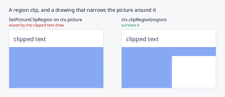
Why not install it on the picture yourself
ctx.picture is a real RENDER Picture and a region can be hung on it with
fixes.SetPictureClipRegion(ctx.picture.id, region, 0, 0) — which works,
right up until ntk next draws under a rectangular clip.
A Picture holds exactly one client clip, and ntk's own fast paths use it:
text glyph runs, batched fillRects, rounded boxes and drawImage all narrow
the picture to a rectangle around the drawing and put it back afterwards. Any
region in that slot is overwritten, silently, and which drawings do it depends
on which internal route they take (issue
#292).
Reading ctx.picture does settle the slot first, so a region you install
right after one is not fighting a rectangle left over from the last drawing —
but the next drawing takes the slot back.
clipRegion() is the same region as a clip ntk knows about: it is part of the
save()/restore() state, the fast paths intersect with it and restore to
it, and "no clip" is a state the context tracks rather than a full-plane
rectangle it stamps over whatever was there.
How curves are flattened
Everything curved is a polyline by the time it reaches a rasterizer, and how
many segments that polyline has decides the cost of everything downstream:
roughly a trapezoid per edge for a fill, a pair of triangles per segment for
a stroke. The budget is a flatness tolerance — the furthest the polyline
may stray from the true curve, 0.25 device pixels by default and the last
argument of flattenPath(cmds, matrix, tol).
Curves get there two ways:
- Beziers —
bezierCurveTo,quadraticCurveTo, SVG curve data, font outlines — are bisected until each piece is flat enough. The test is the guaranteed bound on how far a cubic leaves its chord, three quarters of the larger control-point distance, plus a check that the curve does not run past either end of the chord: a piece whose handles point back down the chord can hug its line while overshooting an endpoint and returning, which is within tolerance as a set of points but traversed in the wrong direction — invisible in a fill and a spike in a stroke. - Arcs —
arc,ellipse,arcTo,roundRect, SVGA— lower to cubics but remember the arc they came from, and are split into equal angular steps straight from the sagitta: a chord spanningθof a circle of radiusRmisses byR·(1 - cos(θ/2)), so the fewest chords isceil(sweep / 2·acos(1 - tol/R)). Bisection could only land on powers of two and overshot this by up to 2x — a quarter circle at r=256 took 32 chords where 18 are within tolerance.
The arc tag carries the ellipse as a centre plus two semi-axis vectors, which an affine map takes to the same form, so the exact route survives any transform — rotation, non-uniform scale and shear included — and the tolerance is always measured in device pixels. Ellipses are bounded by their semi-major axis, which is exact for circles and conservative for eccentric ones. Arc endpoints stay bit-identical to the lowering, so a rounded corner still meets the straight edge it joins.
A consequence worth knowing: the flattened polygon is inscribed, so a
filled circle is short of πr² by up to what the tolerance allows (~1.6% at
r=20) and never larger. Pass a smaller tol where that matters.
Where drawings are rasterized
Every fill and stroke ends the same way: coverage lands in a scratch a8 mask
bounded to the drawing's ink (one mask per cluster of its pieces — see
below), the mask is
intersected with the clip and globalAlpha, and the fill style is composited
through it. Only the first step has a choice of where it happens.
- Server-side — the geometry is trapezoidated here
(
lib/trapezoid.js) and sent asAddTraps/Triangles. Cost grows with geometric complexity: per-request overhead plus 40 bytes per trapezoid. - Locally — the geometry is rasterized into 8-bit coverage here
(
lib/precise.js) and uploaded with onePutImage. Cost grows with area: one byte per pixel of the drawing's bounding box — or, under a clip, of the part of it inside the clip's extents, the only part uploaded and composited. The coverage is still rasterized over the whole box, so a drawing that different clips split across passes gets the same bytes in every one of them.
Both routes draw the same mask, to the byte. The local rasterizer,
PreciseRasterizer, samples the way RENDER's default poly-mode, Precise,
defines: a grid of 17 × 15 sample points per pixel, each trapezoid or
triangle added into the mask. It samples them from the same 16.16
trapezoids and triangles the server route would send. That is how pixman
rasterizes them, and pixman is what fb (Xvfb, XQuartz) and glamor (Xorg,
Xwayland) use. So which route a drawing took never shows, wherever the same
pixels are drawn more than once:
- a pass over part of the window that strokes only the run of an edge inside its clip, against a repaint that strokes all of it;
- a stroke drawn straight to the window (no clip, no round cap or join, full
alpha,
source-over, which skips the mask altogether), against the same stroke under a clip; - a clip mask, against a fill.
With the analytic ScanlineRasterizer, the default before it, the local
route was a few levels away from the server at every edge, and those seams
showed (issue #462). A server that does not rasterize with pixman can still
differ from the local route; a pixman server cannot.
node-x11's in-process JS X server, which the hermetic tests and the
website's playground run on, rasterizes trapezoids its own way, so there the
two routes still differ by a few levels at the edges.
The choice is per drawing, made by routeRaster() from the bounding-box area
and the flattened edge count. Defaults, measured against XQuartz with shapes
bracketing the range (a rounded rectangle at 14–79 trapezoids, a stroked icon
at 181–1053):
{ maxArea: 64 * 64,   // at or below this bounding-box area, always local
  bytesPerEdge: 150,  // above it, local while area <= 150 * edges
  maxBytes: 1 << 20 } // never upload more coverage than this at once
An icon-sized drawing takes the local route, and a wall of 400 of them costs ~24 ms of server time instead of ~1.9 s. A large, geometrically simple shape (a full-window rounded rectangle) takes the server route, where a handful of trapezoids beat a megabyte of coverage.
The same choice covers the a8 mask a non-rectangular clip builds: a
clip() whose path is not a rectangle rasterizes its coverage into a temp the
size of its bounding box, locally or as trapezoids, by the same policy. A
rectangle-only clip stack still rasterizes nothing at all, so this is only
reached by rounded corners and genuine paths. It matters where trapezoids are
a software fallback: a screen of
rounded cards can hold more clip masks than fills, and before this they were
the one drawing no policy could move.
Because what crosses the wire is coverage, not colour, the route is
invisible to everything else: gradients, solid fills, globalAlpha, clip and
composite ops all work identically either way, and a widget that draws through
fill()/stroke() — SvgView, anything of your own — is routed
without knowing this exists.
Many pieces in one path: what the mask costs
The mask is sized to the drawing's ink bounding box, and it costs width × height whatever the coverage inside it is. For one shape that bound is right. For a path holding N disjoint subpaths — a graph's edges, a scatter of handles, a wall of icons — the bound is their union, so batching N draws into one path trades N small masks for one big one. Whether that wins depends entirely on whether the pieces span the box anyway, and the two answers are far apart (measured at 1100×700 against XQuartz, per frame):
| scene, batched into one path per pen | one mask | clustered | drawn singly |
|---|---|---|---|
| 735 long edges | 1 mask, 0.73 MB, 27 ms | unchanged | 735 masks, 64 MB, 326 ms |
| 19 edges + 40 handle discs | 2 masks, 1.42 MB, 5.1 ms | 25 masks, 0.74 MB, 3.9 ms | 59 masks, 1.58 MB, 7.0 ms |
Long edges win from batching because each already spans a big box — the union adds nothing. Scattered dots lose: their coverage is ~1% of the union box, and the mask pays for all of it.
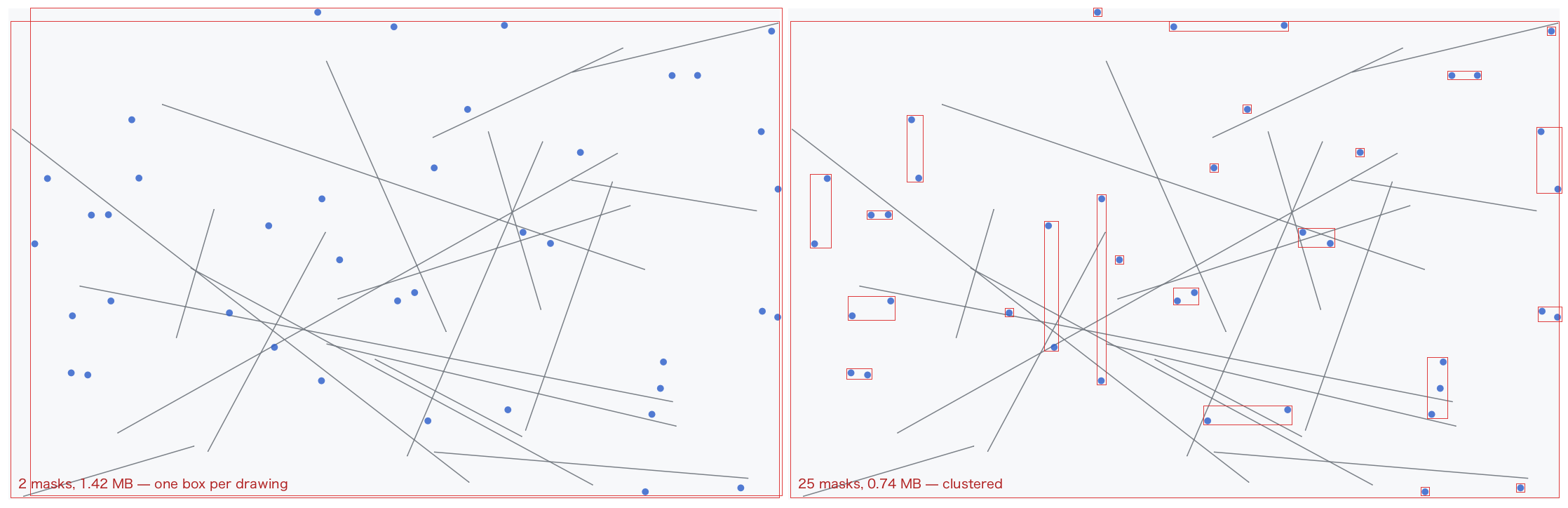
The boxes above are the masks themselves (scripts/bench-mask-clusters.mjs --png): on the left the two a8 masks a batched frame used to cost, on the
right the same drawing's clusters. The stroked edges keep one box — they span
it — while the handles each get their own.
So the choice is made per drawing rather than left to the caller. The pieces'
boxes go through a greedy gap partition (lib/maskcluster.js) and the mask is
emitted once per cluster:
- a cut is only made where nothing straddles it, which is what keeps every cluster box disjoint from every other. Disjoint boxes are why the split is invisible: no pixel is composited twice (a translucent colour would blend twice at any overlap), and the winding number a fill rule asks for does not change, because a closed subpath contributes nothing to the winding of a point outside its own box;
- and only where it saves more mask area than the extra mask pass costs.
Every cut therefore removes at least
minSavingpixels of mask, which also bounds how many clusters a drawing can take.
The upshot for a caller is that "fewer, bigger draws" stays the right instinct: where the pieces span the box, nothing is split; where they are scattered, the box around all of them is never paid for.
app.maskPolicy = { minSaving: 64 * 64, // mask pixels a cut must save to pay for its pass
                   maxMasks: 32 };     // most clusters one drawing may take
app.maskPolicy = { maxMasks: 1 };      // one mask per drawing, whatever it holds
Two things it deliberately leaves alone. Composite ops that write outside
their coverage — copy, source-in, destination-in, source-out,
destination-atop — keep one box, because for those the gaps between boxes
are pixels a single mask would have written too. And a source-over stroke
with no clip, no round caps or joins and globalAlpha 1 never builds a mask
at all: its triangles composite straight onto the destination.
ctx.maskStats is { masks, pixels, split } — mask passes, their total area,
and how many drawings took more than one. Mask area is the cost with no other
symptom, so it is counted rather than inferred;
scripts/bench-mask-clusters.mjs prints the table above with the split on,
forced off, and against drawing the pieces singly.
Rounded rectangles: corner glyphs
A third route sits in front of both of the above and skips rasterization
entirely. A fill() or stroke() whose path is exactly one roundRect() on
integer, axis-aligned geometry is recognized and emitted as corner glyphs +
FillRectangles: the box's only curved ink — the corners — becomes XRender
glyphs, cached server-side after first use and keyed by (radius, border width, corner) but not by the box size, so an animating pill or progress
bar keeps its glyphs while the rectangles stretch. Only the top-left corner of
each family is ever rasterized; the other three are mirror flips of its
bitmap, which also makes the four corners of a box pixel-exact mirror images.
The straight runs between the corners are plain FillRectangles. A steady
state card — background plus 1px border — is 4 small requests (two
CompositeGlyphs, two FillRectangles), with nothing rasterized and nothing
uploaded. The pieces partition the pixels, so translucent colours composite
once, never twice.
The recognizer only fires when it can reproduce the polygon route's output:
- the path is one
roundRect()(the tag any other path verb clears), drawn under a translate-only transform; - the fill/stroke style is a solid colour (
globalAlphafolds into it) and the composite op issource-over; - box position, size and radii are integers, radii within the policy cap;
- the clip stack is absent or rectangular (applied server-side as a picture clip, the way text glyph runs already do);
- strokes additionally need a uniform circular radius, no dashes, a border
no thicker than the corner radius — and the band's ink on pixel
boundaries:
x ± lineWidth/2integral andlineWidthitself integral, which a border of any width drawn the correct way (path inset by half the width) satisfies. The path radius is free to be fractional — nesting a border inside a background corner of radiusRmeans a path radius ofR - lineWidth/2, half-integer at every odd width, and the corner glyph carries that half pixel the same way the polygon route does. A 1px stroke on integer coordinates is a different shape — a genuine two-row 50% band — and keeps the polygon route. strokeRect()and radius-0 strokes lower further, to 4FillRectangleswith no glyphs at all.
Everything else falls through to the two routes above, unchanged. Every
bail-out is counted on the context — ctx.shapeStats is
{ hits, misses: { gradient, transform, 'clip-mask', fractional, dashes, 'radius-cap', … } } — and NTK_DEBUG_SHAPES=1 prints the process-wide
tally at exit, because a silent fall-off from this route is a perf cliff
worth noticing.
Policy, beside rasterPolicy/textPolicy:
app.shapePolicy = { maxRadius: 64,       // corners above this fall back
                    cacheBytes: 256 << 10 }; // server-side corner-bitmap budget
app.shapePolicy = { maxRadius: 0 };      // disable the route entirely
NTK_NO_SHAPE_GLYPHS=1 in the environment disables it too (for A/B
measurement — examples/rounded-boxes.js and
scripts/bench-rounded-boxes.mjs draw the comparison,
scripts/bench-odd-border.mjs sweeps a bordered card wall by border width
alone, and examples/odd-border.js puts both routes side by side with the
corners magnified, for eyeballing parity rather than timing it). The corner
cache is per connection and evicts by resetting the page
when the budget is exceeded, so an adversarial animated-radius load stays
bounded; a real UI's population (a design system's radii × border widths) is
a few dozen tiny bitmaps that never approach it.
Swapping the rasterizer
import { createClient, ScanlineRasterizer, setDefaultRasterizer } from 'ntk';

const app = await createClient({ rasterizer: myRasterizer });
// or per app, at any time:
app.rasterizer = myRasterizer;
app.rasterizer = null;          // send every drawing to the server
// or process-wide, before any app is created:
setDefaultRasterizer(myRasterizer);
The default is PreciseRasterizer. ScanlineRasterizer, the analytic
one, computes each pixel's exact area instead. It is smoother along
near-horizontal edges, which point sampling resolves to about 16 levels.
But its masks are a few levels away from the server's at every edge, so a
drawing it rasterizes and one the server rasterizes can show a seam where
they meet. The same holds for any rasterizer of your own.
A rasterizer is any object with one method:
rasterize({ polys, triangles, width, height, rule, dx, dy }) → Uint8Array | Buffer | null
- exactly one of
polys(closed polygons[x0,y0,x1,y1,…], filled byrule,'nonzero'or'evenodd') andtriangles(a stroke's triangle soup, whose overlaps must union rather than cancel — caps, joins and segments overlap constantly); dx/dymust be added to every coordinate. Geometry arrives in device space and the grid covers the drawing's bounding box; the offset maps one to the other. It is passed rather than pre-applied because pre-applying means copying every point of every path on every frame. The 2d context always passes whole pixels;- return
width * heightbytes of 8-bit coverage, row-major and unpadded, ornullto decline. Declining routes that drawing back to the server, so a partial implementation is safe — a rasterizer that only understands non-zero fills can returnnullfor everything else and stay correct.
Thresholds are tunable the same way: createClient({ rasterPolicy }) or
app.rasterPolicy, merged over DEFAULT_RASTER_POLICY.
Shared memory (MIT-SHM)
On a local connection ntk moves bulk pixel transfers through shared memory
instead of the X socket, which node-x11 provides with no extra dependency (an
unlinked /dev/shm segment handed to the server; see node-x11's
docs/ext/shm.md). It is used automatically for the transfers that are large
enough to benefit and falls back to ordinary PutImage/GetImage everywhere
else — a remote display, an old server, or a transfer too small to matter:
drawImageof anImageandputImageData— the image upload, above ~64 KB.getImageData/readPixels— the readback, above ~16 KB. This is the biggest win: a plainGetImageships the whole region back over the socket and can stall the server for tens of milliseconds; shared memory skips that.
Nothing in your code changes. Disable it with createClient({ shm: false }),
or plug in a zero-copy provider (see node-x11); app.shm is the helper.
Coverage masks deliberately stay on the socket. It is tempting to also send
the a8 fill mask (the PutImage in the local-rasterization route above) through
shared memory, and to then let routeRaster push more drawings local. Measured,
it is not worth it: coverage is one byte per pixel, so every mask the rasterizer
produces stays under the size where shared memory beats the socket (a full
256×256 mask is 64 KB and saves ~0.1 ms; a typical icon mask saves microseconds
lost in the round trip). The masks large enough to benefit are exactly the
simple, large shapes routeRaster already sends to the server, where a handful
of trapezoids still beat uploading the coverage. So enabling shared memory does
not change DEFAULT_RASTER_POLICY; the coverage path is unchanged.
The default PreciseRasterizer is a port of pixman's trapezoid rasterizer
(lib/precise.js), down to its rounding: it is measured byte-identical
against a pixman server, and test/raster-precise-live.test.js checks it
against whichever server $DISPLAY names. ScanlineRasterizer uses
signed-area accumulation (the font-rs / stb_truetype v2 algorithm) — exact
analytic antialiasing, no supersampling — and it is what glyph bitmaps are
rasterized with, since a glyph has no server route to agree with. Both have
no dependencies and work in a browser bundle. CoverageAccumulator is
exported if you want to drive the analytic one directly.
Path2D
Path2D is exported from the package root and matches the browser class:
import { Path2D } from 'ntk';

const p = new Path2D('M8 8 H56 V56 H8 Z M24 24 H40 V40 H24 Z');
ctx.fill(p, 'evenodd');

const copy = new Path2D(p);          // copy constructor
copy.addPath(p, [2, 0, 0, 2, 0, 0]); // append with an affine transform
- constructors:
new Path2D(),new Path2D(otherPath),new Path2D(svgPathData) - all context path-segment methods (
moveTo…roundRect) plusaddPath(path[, transform])([a,b,c,d,e,f]array or{a..f}object) - SVG path data supports the full grammar —
M L H V C S Q T A Z, relative forms, implicit repeats, compact arc flags; elliptical arcs are converted to cubics. The parser is also exported asparseSvgPath(d) - per the canvas spec, a
Path2Dis transformed by the current transform atfill/stroke/cliptime, while the default path records points as commands are issued
Gradients
const g = ctx.createLinearGradient(0, 0, 200, 0);
g.addColorStop(0, 'red');
g.addColorStop(1, 'rgba(255, 255, 255, 0)');
ctx.fillStyle = g;
createLinearGradient(x0, y0, x1, y1)createRadialGradient(x0, y0, r0, x1, y1, r1)createConicalGradient(x0, y0, angle)— ntk extension (XRender conical gradient)- The gradient's coordinates are user space, resolved against the transform in force when it is painted — not the one that happened to be current when it was created. A gradient written in a node's own coordinates keeps painting in them after the context is translated to that node's origin, and a scaled context scales the ramp with the shape. A transform that collapses (a zero scale) paints nothing, as the canvas spec says
- Fills sample a gradient from where user space's origin lands, or from the point of the surface nearest it. The picture transform — the CTM's inverse, written in 16.16 fixed point — then carries gradient coordinates where the paint is rather than the paint's position times the CTM's downscale, so a box drawn at a fortieth of its size at x 2,200 is drawn like one at the origin, where it used to ask for 88,000. What is left of the limit is the gradient's own coordinates: an inverse that still cannot be written — a scale below 1/32,768, or a surface tens of thousands of units from both user space's origin and the gradient — paints nothing rather than throwing
- Past the outermost stops the gradient clamps to their colours, so a fill wider than the ramp keeps its end colours instead of fading to transparent
- Gradients are uploaded lazily on first use and freed with the context's pictures on GC
Gradients work anywhere a colour does — fillRect, path fills, strokes,
fillText — and go through the clip, globalAlpha and the composite op
like any other style.
Patterns
createPattern(source, repetition) returns a CanvasPattern: a tile the
server repeats across whatever the pattern fills, in the one composite the
fill already costs.
const tile = new Surface(app, { width: 24, height: 24 });
tile.render((c) => {
  c.fillStyle = '#d0d4dc';
  c.fillRect(0, 0, 1, 1); // one dot per 24x24 cell
});

ctx.fillStyle = ctx.createPattern(tile, 'repeat');
ctx.fillRect(0, 0, ctx.width, ctx.height); // one request, no mask
That is the difference a background grid notices. Drawn as paths — one
subpath per dot, batched or not — the grid rasterizes into an a8 coverage
mask the size of its own bounding box, which for a background is the pane,
then uploads and composites it, every frame. Measured at 1100x700 that grid
cost ~700 KB and ~25 ms of a ~100 ms frame (issue #263); as a pattern it is
a tile-sized picture and one Composite, and the cost stops scaling with
the pane. The same applies to checkerboards under transparency, hatched
chart fills and any texture-shaped background.
sourceis aSurface(pixels the server drew), anImage(pixels uploaded from the client), aPixmapor aWindow. A repeating Picture is created over those pixels, so tiling a surface does not change howdrawImagesamples that same surface. A coverage (a8) surface is refused: it has no colour to paint with —drawImageis what paints coverage in the currentfillStyle. AWindowhas to know its depth and its visual first, because that is where the tile's picture format comes from (see Picture formats):await wnd.getGeometry()establishes the depth on any window, andawait wnd.readyis the wait for both on one adopted by id, which ntk has already asked about — see Adopted windowsrepetitionis'repeat'(the default, and whatnullmeans),'no-repeat', or the two XRender modes the canvas spec has no name for:'pad'(clamp to the edge pixels) and'reflect'(mirror every other tile). The spec's'repeat-x'/'repeat-y'are not supported — XRender repeats a source picture on both axes or on neither — and throw with the equivalent: tile with'repeat'and bound the fill to the one row or column of tiles,ctx.fillRect(x, y, w, tile.height)pattern.setTransform(matrix)positions the tile:[a, b, c, d, e, f]or a DOMMatrix-shaped{a, b, c, d, e, f}mapping pattern space to user space. Translating by the scroll offset is what keeps a grid glued to the content under it; a zoom step re-renders the tile and keeps the composite- The pattern is painted in user space, like the gradients above: the transform in force at fill time applies to the tile as well as to the shape, so a scaled context scales its grid. A transform that collapses (a zero scale) paints nothing, as the canvas spec says
- A pattern is sampled from where its tile's origin lands, as a gradient is from user space's, so a tile scaled down far across a wide window is drawn like one at the origin. A repeating or reflecting tile is the same a whole number of tiles along, and is taken from the one under the surface: a grid scrolled 100,000 pixels is still the grid
- Whole-pixel tiling samples with the
nearestfilter — the tile's own pixels, exactly — and anything else (a fractional offset, a scale, a rotation) resamples bilinearly - The repeating picture is created on first use.
pattern.destroy()(orSymbol.dispose, or the GC) frees it; the tile it reads is the caller's, and destroying thatSurface/Imagewhile the pattern lives is safe — X keeps pixmap storage alive as long as a picture references it, though the pixels then stop tracking anything drawn afterwards - A pattern belongs to the connection, not to the context that created it:
one grid tile serves every window on the app, and it outlives
ctx.destroy()
Patterns work anywhere a colour does — fillRect, path fills, strokes,
fillText — and go through the clip, globalAlpha and the composite op
like any other style.
Shadows
The four canvas shadow properties, applied to every drawing operation —
fill, stroke, fillText, fillRect, strokeRect, fillRects,
drawImage and drawGlyphs (so a TextLayout shadows exactly as a
fillText does):
ctx.shadowColor = '#05070a';
ctx.shadowBlur = 7;
ctx.shadowOffsetX = ctx.shadowOffsetY = 3;
ctx.fillText('Specimen', x, baseline);
shadowColor— any colour string or premultiplied array. The default,'rgba(0, 0, 0, 0)', is what turns the whole thing off: a transparent shadow colour skips the path entirely, so an app that never sets it pays one array read per drawing operation and nothing elseshadowBlur— the canvas spec's diameter, not a radius: the gaussian it names has σ =shadowBlur / 2, so a value here looks like the same value in a browser.0(the default) is a hard-edged copy of the shapeshadowOffsetX/shadowOffsetY— in device pixels, and deliberately outside the current transform, exactly as the spec has it: a rotated drawing casts an upright shadow, the way a rotated element'sbox-shadowis upright in CSS. Offsets are rounded to whole pixels when the shadow is composited (the drawing's own sub-pixel position is untouched)
A shadow goes through everything the drawing itself does: the clip,
globalAlpha and the composite operation all apply to it, and it is painted
first so the drawing lands on top. With no offset and no blur it sits exactly
under the shape, where it shows through anything translucent — that is the
spec's behaviour, not an oversight.
How it is drawn, and what it costs
A shadow is the drawing's coverage, blurred, offset and painted in one colour. All three steps are server-side:
- the shape is drawn into a padded
a8Surface— white on transparent, so every pixel is its own alpha - two
convolutionfilter passes blur it, horizontal then vertical - the result composites as a mask with
shadowColoras the source
The padding in (1) is why an app should not assemble this by hand: a convolution samples outside the picture, where RepeatNone reads transparent, so a shape drawn flush to the surface edge ends in a straight line where the kernel ran out of pixels. Everything here pads by the blur's full reach.
Step (2) is two 1d passes rather than one 2d kernel because a gaussian is
separable, and that is the difference between a shadow you can animate and
one you cannot: a k-wide 2d kernel costs k² multiplies per pixel where two
passes cost 2k. At shadowBlur: 30 that is 8281 against 182. It also runs
once: the passes leave the blur in the surface's pixels, where a
convolution filter hung on a picture (picture().setBlurFilter()) is
re-applied by the server on every composite, so a cached blurred picture
re-runs its whole kernel every frame it is drawn.
A wide blur does not run at full resolution. Two passes still cost
2 * taps * w * h, and both factors grow with the blur, so a large soft
shadow is most of what a first paint spends — ten of them on react-x11's
configurator came to 118M multiply-accumulates, 73% of it in two (issue
#338). A gaussian carries no detail finer than about σ/2 px, so past σ 8 the
coverage is shrunk by 2 or 4, blurred at sigma / scale, and resolved back:
scale off the kernel, scale² off the area, and a difference from the
exact blur of at most three levels of 8-bit alpha. Nothing downstream sees it —
the surface is the size it always was and still carries no filter, so a
cached shadow composites exactly as before. scaleSigma and maxScale in
the policy below tune it, and maxScale: 1 turns it off.
Step (2) is the one piece worth having on its own, and it is exported as
blurCoverage(coverage, sigma) for a toolkit
that draws its own shapes and wants only the blur — the padding rule, the
sigma-is-half-the-radius rule and the bake-don't-filter rule are all there.
Text shadows are cached — keyed by (text, font, blur) on the connection — because text is the one drawing with a short, stable name. A label redrawn every frame, or a specimen redrawn on every slider tick, builds its coverage once and composites it afterwards.
A rectangle's or a rounded rectangle's shadow comes from a tile. A
blurred fill of a path that is one rect() or one roundRect() — circular
or elliptical corners — or, filled 'evenodd', one inside another (the
frame an inset box shadow is cast around), and a blurred fillRect, is not
blurred where it is drawn. Its shadow is the same all along its straight
edges wherever they are and however long, so it is made once, for a copy
of the shape shortened to three pixels of straight edge on each axis that
has room, and drawn as up to nine pieces of that tile: the corners as they
are, the straight pixel stretched between them. The tile is named by the
corners, the blur and the hole — not by where the shape is, how long its
sides are, or which part of it a paint reaches — so every card on a page
with the same shadow draws from one, a strip a scroll exposes across a
shadow composites a strip of it, and none of it runs a server blur. It is
kept with the other shadow coverage (cacheBytes), made in JavaScript from
the shape's exact coverage and a gaussian of σ shadowBlur / 2, and a wide
blur's tile is made at a half, a quarter, … of the size, as a wide blur is
above, and scaled up as it is drawn. It is uncapped by maxSigma: what a
tile costs is bounded by that scale. On XQuartz a header's
box-shadow: inset 0 0 100px repainted by a scroll's exposed strip went
from 31 to 52 frames a second. The plan and the pixels have no X in them and
are exported as ntk/shadow-tiles, which react-x11 draws its CoreGraphics
and Direct2D shadows from too.
A shape under a transform that rotates, skews or mirrors, and any other
path or image, still blurs its coverage per draw — a large blurred path in a
render loop is the shape to watch for; draw it into a Surface yourself,
with blurCoverage if the blur is the expensive
part, and drawImage that instead.
Laid-out text is cached too, on the identity of the runs it is made of
rather than on a string: a whole paragraph is one coverage surface, whatever
its line count, keyed by those runs and their positions relative to each
other. So the same words wrapped to two different widths are two shadows —
they are two drawings — while re-drawing one TextLayout, anywhere on the
target, is a lookup and a composite. A caller that hand-builds fresh runs
every frame (a terminal grid, say) has nothing stable to key on and pays for
its coverage each time.
A text shadow moves with its text. Drawn whole pixels away, by a
translate or its own x/y, the shadow of a fillText or a TextLayout
lands exactly that many pixels away, from the same cache entry. So a
renderer that copies pixels it already drew, a scroll blit, still matches a
repaint byte for byte, as it does for the glyphs (issue #350). The anchor
rounds the way a glyph origin does: snapped to 1/256 px, with its whole
pixels split off before the offset is added. That lands a shadow differently
from plain rounding only where its anchor is within 1/512 px of a half pixel.
A shadow belongs to a drawing call, here as in a browser: a paragraph
whose spans change colour is drawn as several glyph composites, and each
casts its own shadow, exactly as consecutive fillTexts would.
app.shadowPolicy tunes the ceilings (partial objects merge over the
defaults):
cacheBytes(4 MB) — LRU budget for retained shadow coverage; least-recently-drawn surfaces are freed server-side past itmaxSigma(32) — the widest gaussian actually run. The kernel is 6σ+1 taps, every tap rides the request, and the server multiplies each of them per pixel per pass, so an unboundedshadowBlurwould be an unbounded stall. This is the one place a shadow stops matching a browsermaxPixels(8 M) — the largest coverage surface built for one shadow; past it the shadow is dropped and the drawing is unaffectedscaleSigma(4) — the σ a reduced-scale blur may not fall below. The coverage is shrunk by the largest power of two that keepssigma / scaleat or above this, so a blur under σ 8 runs exactly as before. The error is a property of that reduced σ rather than of the ratio: three alpha levels at 4, four at 3, seven at 2maxScale(4) — how far that shrink may go whatever the floor allows.maxScale: 1blurs everything at full resolution, which is what 8.6 didtiles(true) — whether a rectangle's or a rounded rectangle's shadow comes from a tile, as above.falseblurs every shadow where it is drawn
Only what could be seen is rendered: a shape's ink is clipped to the part whose shadow can land on the target at all (its own bounds, moved back by the offset and grown by the blur's reach), so a shape mostly off-screen does not allocate a surface the size of its bounding box.
How strong a shadow gets, and how to test one
A blurred shadow reaches shadowColor only where the shape casting it is
wide compared with the blur. That follows from what a blur is — coverage
convolved with a gaussian — but it surprises people looking at pixels, so
here it is in numbers, with σ = shadowBlur / 2:
| what casts it | shadowBlur | peak alpha |
|---|---|---|
| a 60×40 rect | 30 (σ 15) | 0.78 |
| a 60×40 rect | 8 (σ 4) | 1.00 |
| 48px glyph stems | 14 (σ 7) | 0.37 |
A glyph stem five pixels wide against σ 7 keeps about erf(5 / (2√2 · 7))
of its coverage — under a third — and that is what a browser draws too. So
an exact-colour pixel assertion is the wrong test for a shadow: a
"count the pixels within 90 of #ff0000" check finds nothing on a canvas
whose red glyph shadow is plainly visible, because no pixel on it is ever
that red (issue #287).
What to assert instead:
- the shadow's own alpha, on a transparent target. Draw with
fillStyle = 'rgba(0, 0, 0, 0)'so only the shadow paints, and read the alpha channel out ofgetImageData— it is the coverage, with no background mixed into it - a difference between two places, rather than a colour: darker (or more tinted) where the shadow is than where it is not, at an offset the drawing itself does not reach
- the profile, when the blur itself is what is under test: a blurred
straight edge follows the gaussian's CDF, so coverage at ±σ is
0.841 / 0.159 (this is what
test/shadow.test.jsandtest/smoke-canvas.test.jscheck)
None of this changes with the server. Shadows render identically on node-x11's in-process JS X server and on Xorg — same requests, same pixels — and both suites pin the same numbers; see xserver.md.
Text
Text is fully shaped: OpenType kerning and ligatures, contextual forms for
complex scripts (e.g. Arabic), bidi reordering and automatic font fallback
all apply. Glyphs upload to the server once per (face, size); drawing costs
about a byte per glyph afterwards. Very large (>256px by default),
fractional or frame-to-frame-varying sizes render as trapezoids instead —
no per-size server cache — see
text.md; tune via
app.textPolicy.
fillText(text, x, y)— draws with the currentfontandfillStyle, honoringtextAlign/textBaseline, and composites as every other drawing does: the clip,globalAlpha,globalCompositeOperationand the shadow all applymeasureText(text)→ canvas-style TextMetrics:width,actualBoundingBox{Left,Right,Ascent,Descent},fontBoundingBox{Ascent,Descent}textAlign—'start' | 'end' | 'left' | 'right' | 'center'textBaseline—'alphabetic' | 'top' | 'hanging' | 'middle' | 'bottom' | 'ideographic'fontVariationSettings—'"wdth" 87.5'or{ wdth: 87.5 }, for a variable font. Thewghtaxis needs none of this: a numeric weight in thefontshorthand already drives it (ctx.font = '460 40px Inter'). Set either before or afterfont— see fonts.mdfontOpticalSizing—'auto'(default) sets a variable face'sopszaxis at the size the text is drawn at, as CSS'sfont-optical-sizingdoes;'none'leaves it at the font file's own default. Order-independent likefontVariationSettings— see fonts.mdlayoutText(content, options)→TextLayout— ntk extension: wrap text (or styled spans) to a target width without drawing, inspect lines and metrics, thenlayout.draw(ctx, x, y)drawGlyphs(op, src, positioned)— ntk extension: composite glyph runs directly, shaped or hand-built. The run shape is public API, for renderers that position glyphs themselves (a terminal grid, a tabular column) — see text.md.srcis a colour,nullforfillStyle, or a picture — see text.mddrawTraps(op, src, traps)— ntk extension: composite trapezoids under the clip andglobalAlpha, asdrawGlyphsdoes glyphs, withsrcthe same.trapsis a flat array of six device-space numbers a trapezoid, as RENDER'sAddTrapstakes them: the left x, right x and y of its top edge, then of its bottom edge
Custom font files: app.fonts.load(path), then use the family name in
ctx.font. See text.md for the full text API and
fonts.md for font lookup.